A charger that terminates correctly on the designer's bench with a golden sample still has to prove it safe across every cell state, fault and ambient it will meet in a million homes. This validation paper maps the test programme for a consumer nickel-metal hydride charger, anchored in EN 60335-2-29 (the European adoption of IEC 60335-2-29 for battery chargers), and shows how to combine safety-standard testing with termination-robustness and joint cell-charger endurance so that the certified product is also the durable product. It is the bridge between charger electronics and the IEC 61951-2 and IEC 62133-1 evidence for the cells.
A household battery charger is an electrical appliance, and within the Low Voltage Directive framework its safety is assessed to the EN/IEC 60335 family, with Part 2-29 giving the particular requirements for battery chargers. The standard addresses normal operation, construction, protection against electric shock and thermal hazards, and abnormal and fault conditions, alongside the EMC requirements that apply separately. A charger sold with NiMH cells also interacts with the cell standards: the cells carry IEC 61951-2 performance and IEC 62133-1 nickel-system safety evidence. The first documentation task is to keep these three threads - appliance safety, cell performance and cell safety - clearly linked rather than merged into a single vague 'CE' claim.

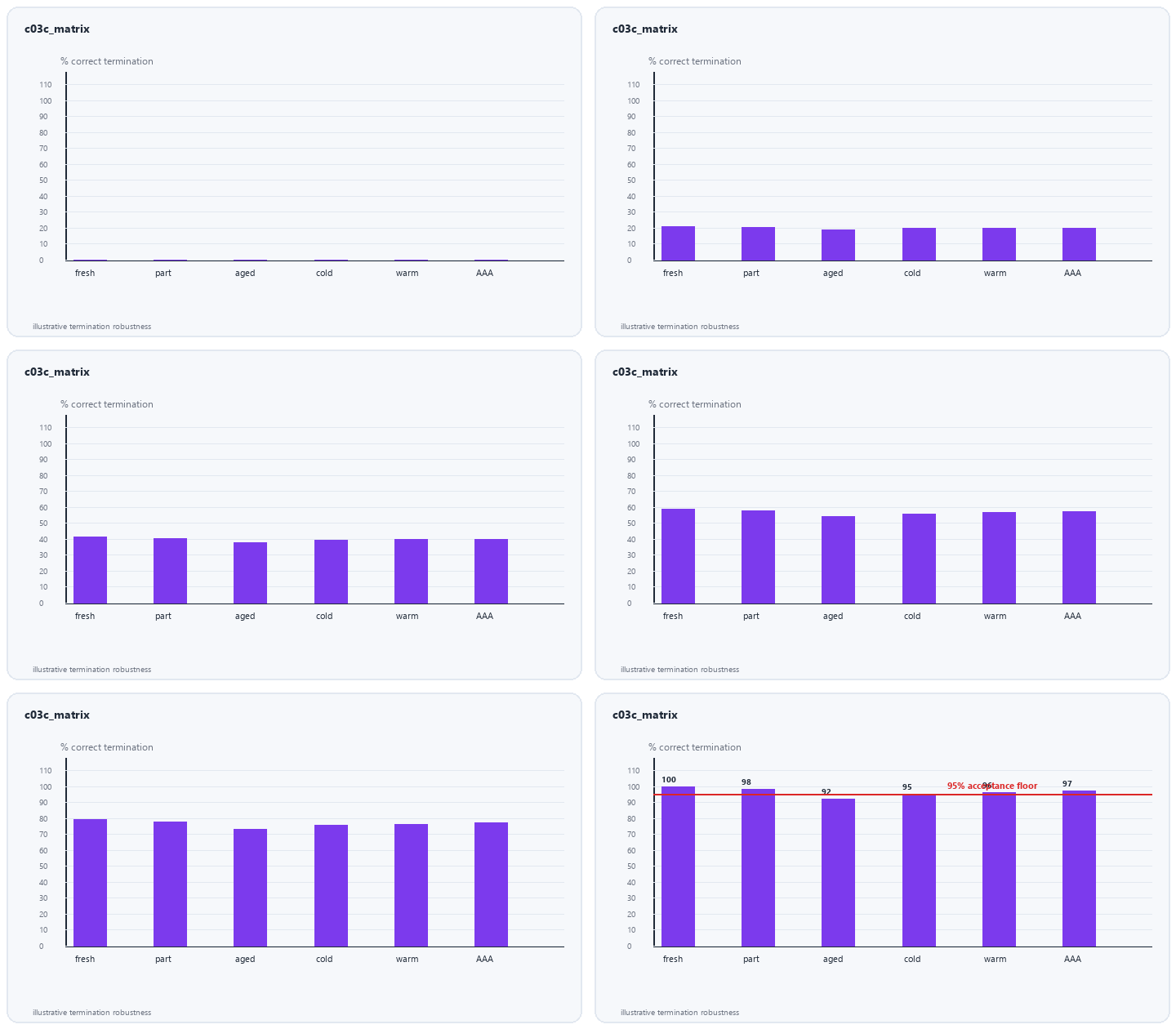
Termination must be validated not only with a fresh, nominal cell but across the whole envelope it will encounter: fully discharged and partially charged cells, highest and lowest supported capacities, AA and AAA, cells at the cool and warm edges of the specified ambient, and aged cells whose voltage signature has flattened. For each condition the test records time-to-terminate, peak cell temperature, whether -dV, 0dV, dT/dt or timer actually ended charge, and the overcharge energy delivered after true full. A robust design terminates by the intended primary signal on fresh cells and falls back predictably to timer or temperature on difficult ones, never relying on luck to avoid sustained overcharge.
The safety case is built on what happens when things go wrong: a reversed cell, a shorted bay, a cell that will not accept charge, a blocked sensor, a loss of the temperature probe, an input over-voltage, and prolonged connection well beyond normal charge time. EN 60335-2-29 abnormal-operation testing requires the charger to fail safely - no fire, no rupture, no inaccessible live part, temperatures bounded by the standard's limits. Each fault is injected with the worst-case cell and input, and the design's independent timer and absolute-temperature cut-offs are precisely what make these tests pass; removing them to save cost is the classic route to a field incident.
In a four- or eight-bay charger all channels rarely behave like one. Simultaneous fast charge raises the internal ambient, which changes each cell's dT/dt signature and can cause premature or delayed termination; a cell in the centre bay runs hotter than one at the edge. Validation therefore includes thermal mapping under full-load simultaneous charge, worst-case high ambient, and the maximum supported capacity, confirming that every bay still terminates within temperature and time limits. The animated evidence stack below sequences the joint test layers from termination robustness through abnormal faults to cell-standard cross-reference, mirroring how a certification reviewer reads the file.
The most revealing - and most often skipped - test is joint endurance: cycle matched cells through the actual charger for hundreds of cycles and measure capacity fade, internal-resistance growth and retention against IEC 61951-2 methods. This catches mismatches that component-level tests miss, such as a maintenance current that looks small on the schematic but erodes LSD retention over months of docked storage, or a termination threshold that overcharges aged cells. Co-testing also generates the evidence to substantiate the consumer-facing 'up to N recharges' claim, because that number is a property of the cell-charger pair, never of the cell alone.
A complete charger validation record combines the EN 60335-2-29 safety report and LVD/EMC declarations, a termination-robustness matrix across the cell envelope, fault-condition results, multi-bay thermal maps, joint cell-charger cycle endurance, and the cross-referenced IEC 61951-2 and IEC 62133-1 cell reports. Presented together they answer the retailer's three questions in order - is it safe to sell, does it charge every supported cell correctly, and will it preserve the advertised life. Building the dossier in this order during development, rather than assembling it after a design is frozen, is how a manufacturer turns regulatory compliance into a genuine market-quality asset.
Weijiang Power validates matched NiMH cell-charger programmes to EN 60335-2-29 with termination-robustness, fault and multi-bay thermal testing plus joint cycle endurance cross-referenced to IEC 61951-2 and IEC 62133-1. Share your charger design and target cells and we will build the joint validation plan and dossier.


